Monday, 30 December 2013

Non-Periodic Tiling in Blender, Chapter 2

A few months ago, I made a post about Penrose Tiling in Blender. Remember how I mentioned that Penrose Tiling is a kind of non-periodic tiling? Well, I'd now like to show you another Blender script I made. This one is able to generate hundreds of kinds of non-periodic tilings (including Penrose Tiling).

You see, I've stumbled across an excellent website, one Tiling Encyclopedia which archives almost two-hundred non-periodic patterns. I was delighted to discover that most (if not all) of the listed patterns can be generated using simple substitution algorithms. What's a substitution algorithm? Well, allow me to explain myself with an example: the Kite-Domino (discovered by D.Frettlöh and M. Baake). There's only two kinds of tiles: "Kites" and "Dominos".

These are the substitution rules which generate the Kite-Domino. As you can see, the algorithm is simple enough to summarize in a single image.

Any place you have a Kite prototile, replace it with the designated configuration of kite and domino prototiles. Likewise, the domino prototile has it's own substitution rule.

After several iterations of substitution, you can turn a single domino into an extremely complicated pattern.


Here's another one: the Goodman-Strauss 7-Fold Rhomb, named after it's discoverer, C. Goodman-Strauss.

I found this one particularly beautiful, and it's the one which initially motivated me to code my tiling script.


This time, there's three rhombus prototiles. I had to do a bit of math to figure out how to model them: it turns out that each rhombus has an angle 180/7.0 times 1, 2 and 3 respectively (hence "7-Fold Rhomb" I suppose?).


As you can see, this pattern uses the same kind of substitution rule. The only difference is that this time, you need to be a little more careful when building your substitutions because the orientation of the tile is important. Notice that little arrow markings were added to the shapes - these indicate the orientation of the tiles.

Most, if not all of the patterns documented in the Tiling Encyclopedia can be generated from a substitution rule. Naturally, I decided to find a way to build a set of substitution rules into Blender and use them to generate patterns. Read on to find out how this works.


Tutorial

My script is available at the end of this post.

Let's pick an interesting pattern to build ... say, the Pinwheel (discovered by J. Conway and C. Radin) ... it's apparently famous enough to have a wikipedia article. The prototile substitution rules are given on the right.

We need to:

  • Model the prototiles
  • Define the substitution rules
  • Set the initial conditions
  • Run the script
Build the Prototiles

If an object has a name of the form [shapeName].###, my script will treat them as an ordinary prototile of type [shapeName].

In building the Pinwheel, I used two prototile types: Triangle and TriangleRev. Both are triangles with side lengths 1:2:√5, and mirror images of one another.

It should be possible to build the Pinwheel with only one prototile, but my script seems unable to properly mirror tiles (i.e. work with objects that have negative scale on one axis). Until this gets fixed, we can workaround by using a second prototile as the mirrored shape.

  
Build the triangle and it's mirror image as separate objects. I suggest you name them Triangle.000 and TriangleRev.000. The former is depicted above.

Model the triangles however you like, but make sure that the width of their base is double their height. I chose to model them aligned with the x-z plane, and with a height of 1. I also chose to build the narrow corner of both prototiles at their respective object's origin/center.


Define the substitution rules
 
A substitution rule will be represented by an object (named SubRule_[shapeName]) and the tiling of objects parented to it. The children, (named Sub_[shapeName].###) will inform my script where to put the new tiles when substituting the old one. We do this by scaling down the "Sub" tiles, and fitting them over top the "SubRule" object, filling its area. We basically are going to reconstruct the substitution rule diagrams, one for each prototile.

To build the SubRule objects, I duplicated the Triangle and TriangleRev prototiles, and re-named them as SubRule_Triangle and SubRule_TriangleRev respectively. If you like, you can store different SubRule objects on separate layers. When my script finds these two objects, it will understand that these objects are involved in defining substitution rules for tiles of type Triangle and TriangleRev. Save yourself the headache, and clear any scaling or rotation from these objects.

I built the Sub objects from more duplicates of the prototiles. These objects were named Sub_Triangle.000, Sub_Triangle.001 ... Sub_TriangleRev.000, Sub_TriangleRev.001 etc. I then scaled them down and started tiling them according to the substitution rule diagram. When positioning these tiles, make sure you're transforming the objects themselves (don't edit the mesh in any way), and make sure these objects are parented to the "SubRule" object.

On the right, I assembled the Triangle substitution rule. The red, dark orange, and green triangles are named Sub_TriangleRev.### and the yellow and light orange triangles are named Sub_Triangle.###.

You might be asking yourself, how do I transform the Sub tiles into place? 
  • Translation
Positioning the Sub tiles is easy if you translate them with vertex snapping on. Snap tiles into place on the edges, and work inwards towards the middle.
  • Scale
Glancing at the Triangle substitution rule, we can see that the hypotenuse of the red Sub_TriangleRev.### replacement tile should be scaled down from a length of √5 to a length of 1. Blender lets you enter python expressions into an object's transform channels, so, set the scale x, y, and z of all your replacement tiles to 1/sqrt(5).
  • Rotation
If you're looking at the tiles from front view (like I am), rotate the objects on their y-axis only. Key to solving this problem is using some basic trigonometry to find the acute angles of the triangular prototiles: atan(1/2)*180°/pi and atan(2)*180°/pi. By adding or subtracting 90° to one of these two values, you can find the values you need. For example, the red triangle's rotation is atan(2)*180/pi (copy paste it into the y-channel). You can find the green triangle's rotation by adding 90° to atan(2)*180/pi.


SubRule_TriangleRev was built in a similar manner.


Set the Initial Conditions


The hardest is over. Now we only need to place a few tiles so that we can subdivide them. I duplicated the Triangle object twice and arranged them into a square. The tiles are red and green in my picture just so that you can tell them apart. Once they're substituted by my script, the new tiles will inherit the colours designated in the substitution rules.

Run the Script

My script will try to subdivide whatever objects you have selected. Open up the script in the text editor, and click the "Run Script" button. You might have noticed that the script starts getting pretty slow after two or three subdivisions.


The slowdown is another one of my script's shortcomings. I suspect the scene.update() command is the bottleneck, but I'm not sure yet. I have some ideas for optimization/speed-up, but if anyone has any suggestions, I would be delighted to hear from you.

Result

This is roughly what the result should look like. If you merge the tiles into a single mesh and mark all the edges as Freestyle edges, you can outline each triangle.  I prefer this pattern without outlines however - it causes multiple triangles to get lumped into interesting shapes.

So that's it! Venture onwards! Endow your 3D artwork with the manifold bounties of non-periodic tiling! Try out my script. Show me cool stuff that you made! If you have any problems, please don't hesitate to send me questions.


import bpy
import bmesh
from math import *
from mathutils import Vector

# Some borrowed code (Apparently from Nick Keeline's "Cloud Generator") which I again borrowed.
def duplicateObject(scene, name, copyobj):

    # Create new mesh
    mesh = bpy.data.meshes.new(name)

    # Create new object associated with the mesh
    ob_new = bpy.data.objects.new(name, mesh)

    # Copy data block from the old object into the new object
    ob_new.data = copyobj.data.copy()
    ob_new.scale = copyobj.scale
    ob_new.rotation_euler = copyobj.rotation_euler
    ob_new.location = copyobj.location

    # Link new object to the given scene and select it
    scene.objects.link(ob_new)
    ob_new.select = False

    return ob_new


############
### MAIN ###
############

# Number of times to iterate substitution rules. Advice: it often gets very slow after 2-3 iterations.
numIterations = 1

currScene = bpy.data.scenes["Scene"]

# Get list of objects to substitute (from selection)
l_objToBeSubbed = bpy.context.selected_objects
# Initialize a list of objects that will substitute the above objects
l_objWhichSubbed = []

# Get the list of objects which contain the substitution rules.
l_subRuleObj = [item for item in bpy.data.objects if item.name.split("_")[0] == "SubRule"]
# Generate a list of the types of shapes that will be substituted.
l_shapeType = [item.name.split("_")[1] for item in bpy.data.objects if item.name.split("_")[0] == "SubRule"]


for iteration in range(numIterations):
    # Iterate over each object that needs to be subdivided
    for obj in l_objToBeSubbed:
        # Determine the kind of substitution needed for the current tile
        shapeType = obj.name.split(".")[0]
        i_type = l_shapeType.index(shapeType)
        # Get the object which contains the needed substitution rule
        subRuleObj = l_subRuleObj[i_type]
        print("Subbing "+obj.name+" using SubRule "+subRuleObj.name)

        # Get the list of template tiles that will determine where to put the new tiles 
        l_objSubstitutes = subRuleObj.children
        # Initialize a list of new shapes to be duplicated from the teplates.
        l_newShapes = []

        for subst in l_objSubstitutes:
            print("Substitute object: "+subst.name)
            newShapeType = subst.name.split("_")[1].split(".")[0]
            newShape = duplicateObject(currScene,newShapeType,subst)
            l_newShapes.append(newShape)
        # Do this here to speed things up.
        currScene.update()
        # Duplicate the templated pattern of tile objects and place them into the tesselation
        # according to the arrangement of templates stored in the substitution rule.
        for newShape in l_newShapes:
            # Find transforms if parented
            # To optimize, try to use currScene.update() less frequently.

            tMat = obj.matrix_world*newShape.matrix_world
            newShape.location = tMat.to_translation()
            newShape.rotation_euler = tMat.to_euler('XYZ')
            newShape.scale = tMat.to_scale()           
#            # A different way ... it seems just as slow.
#            newShape.parent = obj
#            currScene.update()  # update the matrix_world data
#            loc = newShape.matrix_world.to_translation()
#            rot = newShape.matrix_world.to_euler('XYZ')
#            scl = newShape.matrix_world.to_scale()
#            newShape.parent = None
#            # Set transforms as though parented
#            newShape.location = loc
#            newShape.rotation_euler = rot
#            newShape.scale = scl
           
            # Track the new substitute objects
            l_objWhichSubbed.append(newShape)
           
    # Delete the objects I substituted
    for obj in l_objToBeSubbed:
        obj.select = True
    bpy.ops.object.delete(use_global=False)
    # If we are iterating again, we need to designate the newly created tiles
    # as the objects we want to swap.
    l_objToBeSubbed = l_objWhichSubbed
    l_objWhichSubbed = []
# Select the newly created objects
for obj in l_objToBeSubbed:
    obj.select = True
   

- CG From Space 

Friday, 22 November 2013

Blender Quick Tip: How to set up IK pole vectors without breaking the bind pose


Blender's IK system let's you assign targets (called Pole Vectors) which lets you control the orientation of the bend in the IK chain. But there's a common problem...


Say you're rigging an IK arm.
You need to be able to control the orientation of the elbows, and you do this using IK pole vectors.

But there's a catch, isn't there? When you add the pole vector, your binding pose breaks! That's bad. When you are rigging, Thou shalt honour the bind pose and keep it holy. Preserve it, pure, sanctified and unscathed.

How do we fix this?

Notice that Blender's IK constraint requires that you specify a Pole Angle. By varying this value, you can rotate the elbow around the arm's axis. What value should you put in there? Well, that's the problem. Yes, you can vary it by hand until the elbow is roughly in the binding pose, but if you do it this way, you won't get it exactly right.


To fix this problem, you need to understand exactly what the pole angle is. Check out my diagram.

Line A is the x-axis of the upper arm bone. Line B is drawn from the Pole Target and intersects the IK axis at 90°. The Pole Angle is the angle the IK system will put between lines A and B.

In other words, if the Pole Target is located exactly on the upper arm's positive x-axis, setting the Pole Angle to 0° will put the IK arm into the rest pose.


This is how you can set it up:
  • In pose mode, make sure your entire rig is in its rest pose (select everything, hit alt-S, then alt-R, then alt-G)
  • In edit mode, duplicate the upper arm bone. This will become your elbow target.
  • Keeping the duplicate bone selected, go into pose mode. Move the bone a distance of your choosing along its positive local x axis. Don't get this wrong - it has to be the the local x-axis in the positive direction.
  • Go to menu Pose -> Apply -> Apply Pose as Rest Pose
  • Add the IK constraint to the forearm bone as normal. Use the new bone as a pole vector. Set the Pole Angle to 0°.
Tada! You can flip between pose mode and edit mode, and the arm won't twitch.

Some other notes:
  • You don't have to use a pole angle of 0°. If the Pole Target is on the negative local x-axis, set the Pole Angle to 180°. Put the Pole Target on the positive local z-axis and set the Pole Angle to 90° - whatever it is you need to do.
  • What if you have 3 or more bones in the IK chain? Well, Blender uses the x-axis of the basal-most bone when using the Pole Angle. In a 2 bone arm setup, the upper arm is the basal-most bone.
That's it! Happy rigging!


Wednesday, 13 November 2013

Tutorial: Penrose Tiling in Blender


Building tiling patterns in Blender is pretty easy if you know how to use the array modifier... at least, it's usually easy if the tiling pattern repeats itself over space. For example, you can use the array modifier to construct practically any pattern from one of the wallpaper groups.

But that's not what I'm talking about today. I want to talk about Penrose tiling. Penrose tiling is a non-periodic tiling pattern. This means means it does not repeat itself as you move through space, and Blender's array modifier therefore can't be used to construct the pattern. Instead, I used Blender's scripting tools to do Penrose tiling.
(Edit: Penrose tiling is pentagonally symmetric, and you actually can use the array modifier speed up the process of making pentagonally symmetric patterns- however- this process would still require that you do most of the work by hand. Working by hand is slow, and it's very easy to make a mistake early in the process which later results in the pattern containing "hole")

Check out what I made:


I was surprised that I couldn't find anything online about Penrose tiling in Blender, so I decided to write something up myself.  The scripts I used are adapted from the algorithm described in this blog post I found about Penrose tiling. Please check out the link if you're curious about how the script works. If you want to skip this tutorial and just try out my Blender-adapted version of the script, I pasted it at the end of this post.

The steps of my process:

  • Generate a Penrose patterned mesh with the script
  • Use selection tricks to isolate specific patterns of edges in the mesh
  • Dissolve those edges to make new shapes (stars, diamonds etc.)
  • Edge split the shapes into islands. Separate the mesh into different objects according to shape.
  • The rest. (Solidify, bevel, light, animate, render etc.) 


Start by opening a new blender scene, open up the text editor, copy and paste my script, and press the Run Script button.  The script should generate a ten-sided grey disc in the 3D viewport.  Boring. 


Look at the disc in edit mode (right click to select it, and hit tab to enter edit mode). The disc is actually an interesting pattern of triangles. Less boring!

This is our base pattern. From here, I found a way to pull out more interesting patterns of shapes. Try mine out. If you come up with your own, please show me how you did it!

Go into edge mode (ctrl-tab then 2). If you look, the mesh has edges of three different lengths. Select a short edge, then go to the menu Select -> Similar -> Length.

Due to roundoff error, not all of the short edges are exactly the same length. Because of this, the select similar length command might not get the edges you want. If you play with it's threshold value (see picture below), you should be able to get all of the short edges in the mesh, resulting in a selection that looks like this:

Hit x -> Dissolve Edges to make all the small edges disappear. The mesh should now look like this:


Do the same thing to the long edges. Select all of them and dissolve them.


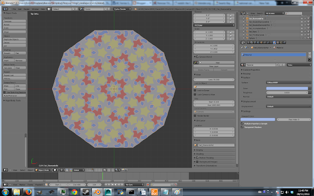
That's the pattern at the top of this post! Cool!

So, at this point, we can start trying to pull shapes out of the pattern using some selection trickery. Warning: do exactly as I say in the order I say it, or it might not work.


Go into face-select mode (ctrl-tab then 3), select a thin diamond, and select -> similar -> area. You should get this:

 Switch to vertex mode (ctrl-tab then 1), and invert the selection (ctrl-i). Deselect the loop of vertices on the edge of the mesh.


You should get this. The center of all the star shapes are selected. Dissolve them! (x -> Dissolve Vertices).


Oo, now you have stars. See? 

We can stillget some more shapes.


Switch to face select mode, and select all the thin diamond faces again. Invert the selection. Switch to edge mode. Invert the selection. Dissolve the edges that remain selected. This trick should merge adjacent pairs of thin diamonds into an angular pac-man-like shape.

One more trick.
There are a few places in the mesh where four fat diamonds make an incomplete star. In vertex mode, select the center vertex of an incomplete star.

Now go Select->Similar->Amount of connecting edges, switch to edge mode, and dissolve the selected edges.


The hard part is over, and the resulting pattern should look like this ->

If you're familiar with Blender, the rest of what I did was pretty straightforward, so I'll be brief.

We don't need to keep all the shapes as a single mesh anymore. Selecting all the vertices (ctrl-a), and edge split everything (ctrl-e->Edge split). Now if you select the stars (and only the stars... remember, use Select->Similar->Area), you can split that set of polygons into a new object (p->Selection). In this way, separate each set of shapes into their own mesh object.

Now we can select between shapes in object mode, and assign different materials (with different colours) depending on the shape.


Above, in this last image, you can see the modifiers I used and their settings.

I put in lights, built in a looping animation, and rendered.  So, that's pretty much it!

One last comment: as you may have observed, Penrose tiling is pentagonally symmetric. Interestingly enough, this is the reason why Penrose tiling is non-periodic. The crystallographic restriction theorem proves that any regularly spaced 2D pattern can't be pentatonally symmetric. Just try it!  If you attempt to create a tiling pattern of regular pentagons, you will fail!.

Now, you might be wondering why the python subdivision algorithm is using the golden ratio, φ. Well, I did some reading, and apparently φ (the golden ratio) appears a lot when you're working with pentagonal symmetry.  This happens because the cosine of 72°( which is one fifth of 360°) is φ/2.


Happy tiling!
~ CG From Space


My Blender-adapted script:


import bpy
import bmesh
import math
from mathutils import Vector

subDivIterations = 6

goldenRatio = (1 + math.sqrt(5)) / 2

def subdivide(triangles):
    result = []
    for color, A, B, C in triangles:
        if color == 0:
            # Subdivide red triangle
            P = A + (B - A) / goldenRatio
            result += [(0, C, P, B), (1, P, C, A)]
        else:
            # Subdivide blue triangle
            Q = B + (A - B) / goldenRatio
            R = B + (C - B) / goldenRatio
            result += [(1, R, C, A), (1, Q, R, B), (0, R, Q, A)]
    return result

# Create wheel of red triangles around the origin
def createWheel():
   
    triangles = []
  
    for i in range(10):
        theta_i = i*2.0*math.pi/10.0
        theta_ip1 = (i+1)*2.0*math.pi/10.0
      
        x_i = math.cos(theta_i)
        x_ip1 = math.cos(theta_ip1)
      
        y_i = math.sin(theta_i)
        y_ip1 = math.sin(theta_ip1)
      
        A = Vector((0.0,0.0,0.0))
        B = Vector((x_i,y_i,0.0))
        C = Vector((x_ip1,y_ip1,0.0))
      
        if i % 2 == 0:
            B, C = C, B  # Make sure to mirror every second triangle
        triangles.append((0, A, B, C))
    return triangles


# Generate map of tiling
listTriangles = createWheel()
for x in range(subDivIterations):
    listTriangles = subdivide(listTriangles)

# Construct the lists necessary for generation of geometry
listVertices = []
listFaces = []
for triangle in listTriangles:
    # write the vertex coords to the list, and remember the vertex indices
    # In Blender, the mesh data stores each vertex as a tuple of 3 floats.
    newVertex1 = (triangle[1][0],triangle[1][1],triangle[1][2])
    newVertex2 = (triangle[2][0],triangle[2][1],triangle[2][2])
    newVertex3 = (triangle[3][0],triangle[3][1],triangle[3][2])
  
    listVertices.append(newVertex1)
    newVertex1_i = len(listVertices) - 1
    listVertices.append(newVertex2)
    newVertex2_i = len(listVertices) - 1
    listVertices.append(newVertex3)
    newVertex3_i = len(listVertices) - 1
    # Define the faces by index numbers. Each faces is defined by a list of the vertex indices belonging to the face.
    # For triangles you need to repeat the first vertex also in the fourth position.
    newFace = (newVertex1_i,newVertex2_i,newVertex3_i)
    listFaces.append(newFace)
  

# Build the mesh in Blender's API

mesh = bpy.data.meshes.new("penroseMesh")   # create a new mesh

ob = bpy.data.objects.new("Pyramid", mesh)      # create an object with that mesh
ob.location = Vector((0,0,0)) #by.context.scene.cursor_location   # position object at 3d-cursor
bpy.context.scene.objects.link(ob)                # Link object to scene

# Fill the mesh with verts, edges, faces
mesh.from_pydata(listVertices,[],listFaces)   # edges or faces should be [], or you ask for problems
mesh.validate(True)
#mesh.update(calc_edges=True)    # Update mesh with new data

bm = bmesh.new()
bm.from_mesh(mesh)
bmesh.ops.remove_doubles(bm, verts=bm.verts, dist=0.001)
bmesh.ops.recalc_face_normals(bm, faces=bm.faces)
bmesh.ops.reverse_faces(bm, faces=bm.faces)
bm.to_mesh(mesh)
mesh.update()

Friday, 8 February 2013

Face Rigging Tutorial, Non-Linear Shape Blending

Welcome to CG From Space!  This is my blog about CG art.

Lately, I've been learning a lot about rigging faces with shapes.  Here are some shots of my latest project:


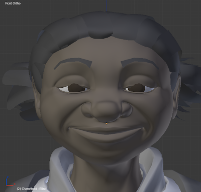
My next picture is an example of a common problem when rigging with face shapes.  It's what happens when you turn on the blink shape to a value of half.

Ew.
Shape blending moves the affected vertices in a straight line, and so they crash through the round eyeball mesh, instead of flowing around it.

This tutorial will show you how to do a shape blending technique called "quadratic interpolation" which allows the affected vertices to move along a curve.  Best of all, this technique also maintains a firm control over the eyelid's shape.

I'll be explaining how to use this technique in Blender 2.65, but it could work in Softimage, Maya, or any other 3D software with blend shapes.  I'll be assuming you already have a general understanding of how to use Blender.

This technique involves quite a bit of math, so I'm going to break this tutorial into two parts: part one will provide basic step-by-step, math-free instructions;  part two will explain the math for those who are interested.

PART ONE – The Math-Free Instructions


Below is a video containing a straight-up demonstration how this technique works.
In it, I rig up a blink for my character "Alto" from my animation Trio Animato


If you can't handle the video's wacky klesmer music, you can read the step-by-step instructions below.


Open up Blender, and load one of your characters.  Make sure that there are enough loops surrounding the eyes, for them to be modified into a blink shape.

1) First of all, we need to create a blink shape.  This shape should allow the upper eyelid to wrap snugly around the entire eyeball.  This is what mine looks like:


2) Create a half-blink shape.  This shape is what your eyeball will look like when it's exactly half-way through a blink. I usually create this shape by setting the "blink" shape to 0.5 and creating a new shape with "New Shape From Mix" in the shape panel's dropdown menu.  I then pull the new shape's vertices outwards until they're resting on the surface of the eye.  Make sure nothing is clipping into the eye.


3)  Create a driver for each shape.  Right click the slider for each shape and pick "Add Driver".


4) The drivers will be mixing these shapes together in some wacky combinations.  In order to give your drivers the freedom they need, change the max and min values for both shapes to +4 and -4.


5)  We need an input for our driver, so let's create a custom parameter, and name it "Blink".  I prefer to store my custom parameters on the "Object" panel.  You can store this parameter on any object that you like, but for now it's probably easiest to store it on your character's face object.


6) We're ready to set up the drivers.  Open the driver editor, and find the shape drivers.  Both drivers should be using the "Averaged Value" of a "Single Property".  Next, set the driver to read in the value of the custom parameter (named "Blink") that we just created.  This can be tricky if you're new to using drivers.  If you stored your custom parameter in an object, select "Obj" in the dropdown menu labeled "Type".  In the next box, select the name of the object that stores your custom parameter.  Lastly, in the box labeled "Path" you need to tell the driver which custom parameter to read (because an object can store more than one custom paramter).  I typed ' ["Blink"] ' in that box (including the [ ] and " ") to tell it to use the custom parameter named Blink.


7) Put a second order polynomial modifier on your driver.  In the above picture, you'll notice that I set the "Blink" driver's polynomial constants to 0.0, -1.0 and 2.0.  Part 2 of my tutorial explains where I got these numbers, but for now you'll have to just believe me.  The "Half Blink" shape driver should also be a second order polynomial with constants 0.0, 4.0 and -4.0.  When you're done, click "Update Dependencies" and Blender will be ready to drive your shapes.

So, that's it!  We're done!  Try it!  Slide the "Blink" parameter between values of 0 and 1, and your character's eye should now blink along a smooth, curved path.


PART TWO – An Awesome Pile-Of-Math

Quadratic Splines

This technique uses quadratic splines, so we first need to understand what they are, and how they work.

What is a quadratic spline?  Well, imagine that you draw three points in space, P1 = (x1, y1), P2 = (x2, y2), and P3 = (x3, y3).  You want to connect these three points using a parabola.  You can do this with a quadratic spline.

That's cool, but how do they work?  Well...

We will define a curve P(t).  We want this curve to trace a parabola as t increases.
We also want the curve to pass through the three points we drew.  Say we wanted P(t) such that:

P1 = P(0)
P2 = P(1/2)
P3 = P(1)

In other words, as t varies from 0 to 1/2 to 1, P(t) will trace a parabola, hitting the points P1, P2, and P3 along the way.  These three points are knows as the "control points".  What does P(t) look like mathematically?  Well, something like this:

P(t) = a2t2 + a1t + a0

The curve P(t) is a second order polynomial in t, with three constants, a2, a1, and a0.  If can we find the values of these constants, we will have everything we need to know for P(t) to work.  We can solve for the constants by plugging in our previously chosen t values.

P1 = P(0)
   = a2(0)2 + a1(0) + a0
   = a0
P2 = P(1/2)
  = a2(1/2)2 + a1(1/2) + a0
  = a2(1/4) + a1(1/2) + a0
P3 = P(1)
  = a2(1)2 + a1(1) + a0
  = a2 + a1 + a0

We now have three equations and three unknowns.  If you remember your high school algebra, it shouldn't be hard to solve for a2, a1, and a0.  If you try to solve it yourself, you should get:

a0 =  P1
a1 =  -P3 + 4P2 - 3P1
a2 =  2P3 - 4P2 + 2P1

Great!  If we take these values and stick them into our definition of P(t), our problem is solved.

P(t) = (2P3 - 4P2 + 2P1 )t2 + (-P3 + 4P2 - 3P1)t + P1


This equation describes exactly what we wanted: a parabolic curve which passes through points P1, P2, and P3 as t varies between 0 and 1.  Try it!  Set t to a value between 0 and 1 and see what you get.

Shapes:

Using the above equation, we can parametrize the movement of a single point P(t) along a parabola.  Shape blending in 3D software can be manipulated in the exactly the same way.  The only difference is that instead of blending a single point along a parabola, we're blending hundreds of points each along their own individual paths.  Say you had three shapes, S1, S2, and S3, and you wanted them to blend together such that each vertex follows a parabola? Well, we just do the same as we did above.

Define:

S(t) = a2t2 + a1t + a0

and we'll constrain S(t) such that it uses three "control shapes",

S1 = S(0)
S2 = S(1/2)
S3 = S(1)

After solving for a2, a1 and a0, we should have the analogous result:

S(t) = (2S3 - 4S2 + 2S1 )t2 + (-S3 + 4S2 - 3S1)t + S1

Now let's re-arrange this equation into a more useful form.

S(t) = S3(2t2 - t) + S2(-4t2 + 4t) + S1( 2t2 - 3t + 1)

Let's take a moment to realize the sheer awesomeness this result contains!  Say you have a character with three shapes.  If you take shape #1 and scale it with the value ( 2t2 - 3t + 1), scale shape #2 with the value (-4t2 + 4t), and scale shape #3 by value (2t2 - t), you will get S(t)!  Changing the parameter t between 0 and 1 will cause the character to morph smoothly from shape #1, then #2, then #3!  Simply create a custom parameter to store the value of t, and use it as an input for the above scaling factors.

You can now understand where I got my number settings for my shape drivers.  I wanted to interpolate from the basis shape (S1), through the "half-blink" shape (S2), and end at the "blink" shape (S3).   I therefore multiplied the "blink" shape with a second order polynomial of the custom parameter, using coefficients 0, -1 and 2, to produce (2t2 - t + 0).  My "halfBlink" shape was likewise scaled with (-4t2 + 4t).  As for S1, my basis shape, I didn't need to do anything because the basis shape is the undeformed shape, which is mathematically equivalent to the "zero" shape.  S(t) therefore doesn't depend on the values that multiply S1.

So, that's it!  You've used quadratic spline interpolation to get a curved path for your shapes!
I hope this has been useful!